|
|
1.IntroductionThe angular momentum of an electromagnetic wave consists of the spin angular momentum manifested through the polarization state and the orbital angular momentum manifested through the spatial distribution of the components of the electric and the magnetic fields.1 Both parts of the angular momentum are mechanically equivalent and can be used to rotate a trapped particle.2 Spin angular momentum can be converted to orbital angular momentum in a nonhomogeneous anisotropic material.3 Beams of light with nonzero orbital angular momentum find applications for optical micromanipulation, quantum information encoding, and control of atoms.4 Surface-plasmon-polariton (SPP) waves are the surface electromagnetic waves guided by an interface of a metal and a dielectric material. The electromagnetic field of an SPP wave is confined to the vicinity of the metal/dielectric interface. This confinement enhances the intensity of the electric field and, thus, leads to the high sensitivity of SPP waves to surface conditions. The high sensitivity is commonly exploited in SPP-based chemical and biosensing devices.5 SPP waves are also exploited in single-molecule detectors,6 optical nanoantennas,6,7 low-loss plasmonic waveguides,8 and integrated optical circuits.9 The angular momentum of SPP waves has not been widely investigated,10 even though some studies have suggested the potential for applications (1) in communications, due to the independence of the spin and the orbital parts of angular momentum;11 (2) for molecular sensing, due to the conservation of total angular momentum;10 and (3) in tunable nanosized plasmonic motors, due to the enhancement of the electric field in the dielectric partnering material near the interface with the metallic partnering material.12 At a given frequency, only one SPP wave—that too of -polarization state—can be guided by a metal/dielectric interface, if the dielectric material is homogeneous.5 The fixed polarization state restricts the choices for the direction of the angular momentum of the SPP wave. With just a single SPP wave available, there is not much room to maneuver the magnitude of the angular momentum either. During the last 5 years, it has been established that multiple SPP waves of the same frequency but with different phase speed, attenuation rate, and spatial field profiles can be guided by the planar interface of a metal and a periodically nonhomogeneous dielectric material—whether that dielectric material is isotropic13–15 or anisotropic16–21—the direction of periodic nonhomogeneity being normal to the interface plane. For example, the partnering dielectric material can be a rugate filter with a sinusoidally varying refractive index,13 a periodically nonhomogeneous sculptured nematic thin film (SNTF),16–20 or a chiral sculptured thin film.21 These developments have spurred the concept of surface multiplasmonics,22 with potential applications for multianalyte optical sensors23 and plasmonic solar cells.24 The present series of papers is devoted to surface multiplasmonics supported by the planar interface of a metal and an SNTF that was fabricated by sinusoidal rocking of a substrate-holding platform during physical vapor deposition in a vacuum chamber. Parts I–III16–18 showed theoretically and experimentally that multiple SPP waves—that differ in phase speed, attenuation rate, and spatial field profiles, but not in frequency and direction of propagation—can be guided by the metal/SNTF interface in the prism-coupled configuration commonly employed to launch and exploit SPP waves.5 Part IV19 was devoted to the underlying canonical boundary-value problem, and Part V20 delineated the surface multiplasmonics phenomenon in the grating-coupled configuration. As the availability of multiple SPP waves with different spatial field distributions may offer a wide range of possibilities for the magnitudes and directions of spin and orbital angular momentums, in this article—labeled as Part VI—we set out to investigate the angular momentums of the SPP waves guided by the metal/SNTF interface in the canonical boundary-value problem. The formulation of the canonical boundary-value problem is revisited in brief in Sec. 2.1, and the methodology to compute the spin and orbital angular momentums is provided in Sec. 2.2. Numerical results are presented and discussed in Sec. 3 when the partnering dielectric material is (1) an isotropic and homogeneous dielectric material; (2) an isotropic dielectric material whose refractive index varies sinusoidally in the direction normal to the interface plane; (3) a columnar thin film (CTF), which is an anisotropic and homogeneous dielectric material; or (4) a periodically nonhomogeneous SNTF of the type considered in Parts I–V. The article concludes with a discussion in Sec. 4. An time-dependence is implicit with denoting the angular frequency and being time. The free-space wavenumber, the free-space wavelength, and the intrinsic impedance of free space are denoted by , , and , respectively, with and being the permeability and the permittivity of free space, respectively. Vectors are in boldface, dyadics are underlined twice, column vectors are in boldface and enclosed within square brackets, and matrixes are underlined twice and square bracketed. The asterisk denotes the complex conjugate, and the Cartesian unit vectors are identified as , , and . 2.Theory2.1.Canonical Boundary-Value Problem of SPP-Wave PropagationLet the half-space be occupied by an isotropic and homogeneous metal with complex-valued relative permittivity scalar , and the half-space by a linear anisotropic nonmagnetic and periodically nonhomogeneous dielectric material with relative permittivity dyadic , where is the period. Without loss of generality, let the SPP wave propagate parallel to the unit vector guided by the interface and attenuate as . In the region , the electric and magnetic field phasors in the metal may be written as13,19 and where , is complex valued, and for attenuation as . Here, and are the unknown scalars with the same units as the electric field, and the subscripts and , respectively, denote the - and -polarization states with respect to the -plane.For field representation in the partnering dielectric material, let us write The components and of the phasors and , respectively, can be found in terms of the other Cartesian components of the electric and magnetic field phasors used in the column vector which satisfies the matrix differential equation where the matrix depends on , , and .13,19,21 The piecewise-uniform approximation technique25 and the Floquet–Lyapunov theorem26 can be used to determine the matrix that appears in the relation for specific values of .Let , , be the eigenvector corresponding to the th eigenvalue of . After ensuring that , we set for SPP-wave propagation, where and are the unknown dimensionless scalars; the other two eigenvalues of pertain to waves that amplify as and cannot, therefore, contribute to the SPP wave. At the same time, can be obtained from Eqs. (1) and (2).Enforcement of the standard boundary conditions across the plane requires that , which may be rearranged as the matrix equation leading to the dispersion equation This equation was solved using the Newton–Raphson method27 to obtain the solutions .2.2.Angular Momentum of SPP WaveThe angular momentum is the moment of the momentum. Any investigation of the electromagnetic momentum must contend with the existence of two different momentum densities: one named after Minkowski, and the other after Abraham.28 Both the Minkowski and Abraham momentum densities are identical in free space, but not in matter. Protagonists of either can point to the experimental verifications of their beloved form and the experimental failures of the other form.29 But, the total momentum density is not under dispute. It can be written as the sum of two parts in two different ways. One way is to represent it as the sum of the kinetic momentum density and the Abraham momentum density, and the other as the sum of the canonical momentum density and the Minkowski momentum density. As Barnett and Loudon30 have put it, “we can identify the Abraham momentum as the kinetic momentum of the light in the medium, while the Minkowski momentum is its canonical momentum.” In experiments of different types, either the Abraham momentum density or the Minkowski momentum density will be measured.31 Thus, the issue is not really Abraham versus Minkowski, but the identification of the one that will be engaged in a specific experiment. As there are two different expressions for the momentum density, there are two different expressions for the angular momentum density.30 Confining ourselves to the -plane, we focused our attention on the time-averaged Abraham angular momentum per unit length (along the -axis) and the time-averaged Minkowski angular momentum per unit length (along the -axis) While writing Eq. (12), we have used the fact that both partnering materials are nonmagnetic. Also, we have assumed that the SPP wave is launched in the plane and travels along the -axis. Finally and .It has now become commonplace to break up the angular momentum into two parts: (1) spin and (2) orbital . Expressions for both in free space are available. In a dielectric material, the time-averaged Abraham spin angular momentum per unit length along the -axis is the same as in free space; thus1 Analogously,32 the time-averaged Minkowski spin angular momentum per unit length along the -axis is given by The orbital counterparts are then obtained simply by subtraction as follows:3.Numerical Results and DiscussionFor all the numerical results presented in this section, the free-space wavelength was fixed at , and the metal was taken to be bulk aluminum: . We normalized , etc., to for convenience. These normalized quantities carry the units of .The integrals over on the right sides of Eqs. (11)–(15) were evaluated analytically for the data reported in Sec. 3.1. For the data provided in Secs. 3.2–3.4, these integrals were interpreted as follows: Analytic expressions were obtained for the integrals over , whereas the trapezoidal rule27 was used for integrals over with a step size of 2 nm. Whereas for the data reported in Sec. 3.3, for the data reported in Secs. 3.2 and 3.4 with selected based on the decay rate of the SPP wave into the partnering dielectric material after ensuring the integrals converged.3.1.Homogeneous Isotropic Partnering Dielectric MaterialLet us begin with the simple case of the partnering dielectric material being isotropic and homogeneous: , where is the identity dyadic. Only one SPP wave, that too of the -polarization state, is guided by the interface of a metal and a homogeneous isotropic dielectric material: . The dispersion equation [Eq. (10)] can be analytically solved to find the relative wavenumber of the -polarized SPP wave: . For the sole SPP wave, we found that and with . Thus, both the Minkowski and Abraham angular momentums of the SPP wave lie wholly in the interface plane and are oriented perpendicular to the direction of the propagation. Furthermore, both are predominantly orbital in nature with the spin and the orbital angular momentums opposing each other. Finally, the magnitudes of the Minkowski spin and orbital angular momentums are higher than those of their Abraham counterparts.3.2.Periodically Nonhomogeneous Isotropic Partnering Dielectric MaterialLet us now suppose that the partnering dielectric material is an isotropic but periodically nonhomogeneous dielectric material with a relative permittivity dyadic where and are the lowest and the highest indexes of refraction, respectively. This material is commonly called a rugate filter.For the numerical results provided in this section, was fixed. The minimum and maximum indexes of refraction of the rugate filter were also fixed: and . Let us note that a homogeneous dielectric material with was used in Sec. 3.1 to permit a comparative analysis with the numerical results obtained in this section. Five values of the wavenumber were obtained by solving the dispersion equation. The values of the relative wavenumber are listed in Table 1, which shows that three - and two -polarized SPP waves can be guided by the metal/rugate-filter interface. Furthermore, one SPP wave of each linear polarization state has a phase speed that is higher than the speed of light in free space—i.e., . The computed values of for the five SPP waves are also provided in Table 1. Table 1Relative wavenumbers q/k0 and y-directed components of ms,oMink,Abr of SPP waves guided by the interface of bulk aluminum (εmet=−56+21i) and a rugate filter described by Eq. (21) with na=1.45, nb=2.32, and Ω=200 nm, when λ0=633 nm. The values of Nd used in Eq. (18) are also provided. The x- and z-directed components of ms,oMink,Abr are identically zero. The computations were made by setting {ap=1,as=0} V/m for p-polarized SPP waves and {ap=0,as=1} V/m for s-polarized SPP waves.
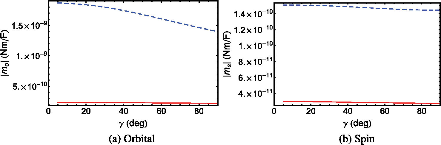
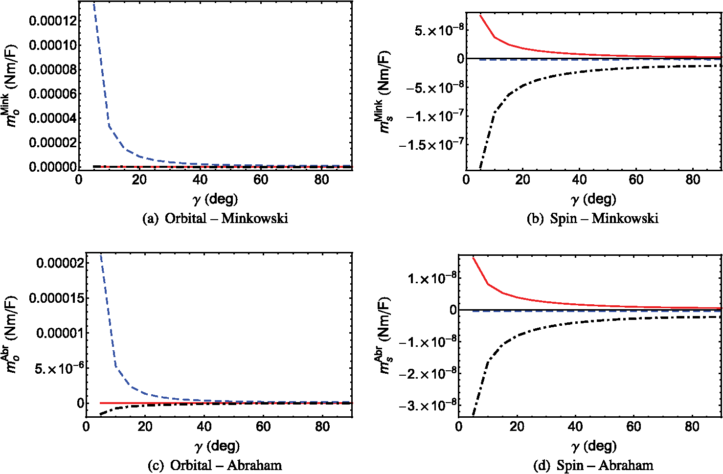
For all five SPP waves in Table 1, the - and -directed components of are identically zero. Furthermore, the magnitudes of the Minkowski spin and orbital angular momentums are mostly higher than those of their Abraham counterparts. Finally, the magnitude of the total angular momentum increases significantly as the phase speed increases (i.e., decreases), whether the Minkowski or the Abraham formulation is used. For all three -polarized SPP waves, is larger in magnitude than in both the Minkowski and Abraham formulations. When , both the spin and the orbital parts of the angular momentum are anti-parallel—just as in Sec. 3.1 for the sole (-polarized) SPP wave guided by the interface of bulk aluminum and an isotropic homogeneous dielectric material. When , the spin and the orbital parts of the angular momentum are coparallel. A comparison of the values of and of -polarized SPP waves in Table 1 with the values in Eqs. (19) and (20) shows that the metal/rugate-filter interface can guide SPP waves with an angular momentum that could be as much as four orders of magnitude larger than of the SPP wave guided by the interface of a metal and an isotropic homogeneous dielectric material. This comparison is justified, because the refractive index of the partnering dielectric material in Sec. 3.1 is the mean of the minimum and the maximum refractive indexes of the partnering dielectric material in this section. For both -polarized SPP waves in Table 1, and are identically zero. Therefore, in both the Minkowski and Abraham formulations, the angular momentum is completely orbital in nature. 3.3.Homogeneous Anisotropic Partnering Dielectric MaterialBefore we proceed to the metal/SNTF interface, let us consider the interface of a metal and a CTF. A CTF is a homogeneous biaxial dielectric material with a relative permittivity dyadic33 where the dyadics depend on the inclination of the columns of the CTF. The third dyadic on the right side of Eq. (22) is stated as so that the morphologically significant plane of the CTF is formed by the unit vectors and , where is the angle between the morphologically significant plane and the direction of propagation of SPP waves. For a CTF made by evaporating patinal titanium oxide, let us use34 where and , for a comparison with the numerical results for a metal/SNTF interface provided in Sec. 3.4.Only one SPP wave can be guided by the metal/CTF interface, irrespective of the angle . The real and imaginary parts of the relative wavenumbers obtained by the solution of the dispersion equation [Eq. (10)] are provided in Fig. 1 as functions of . The SPP wave is neither - nor -polarized, except when . Fig. 1The real and imaginary parts of relative wavenumbers as functions of for SPP waves guided by a metal/CTF interface. The metal is bulk aluminum, whereas the chosen CTF is described in Sec. 3.3. 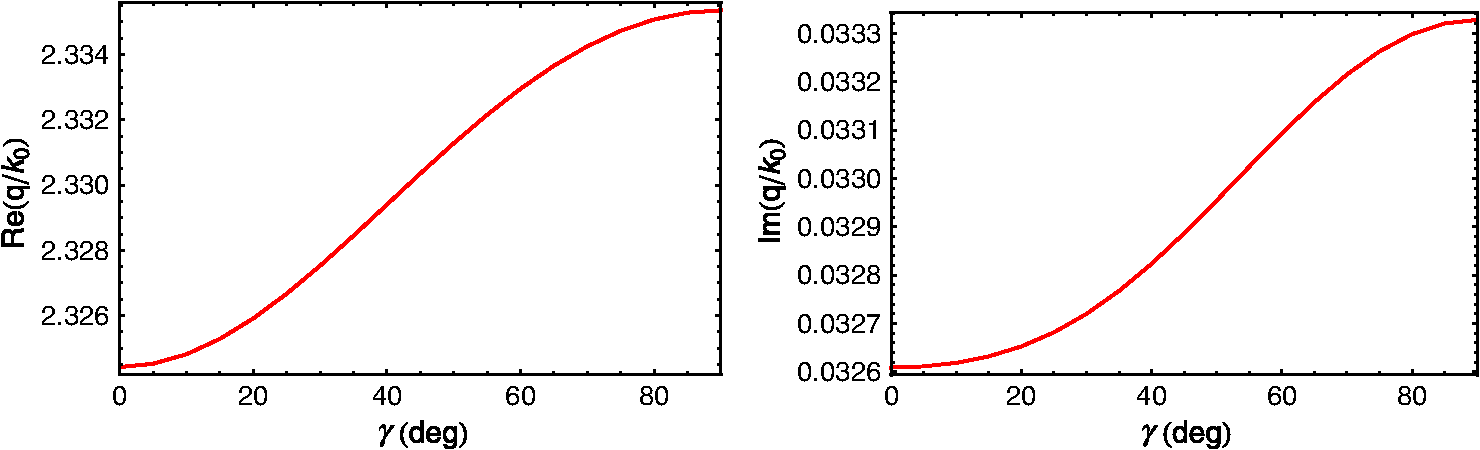 3.3.1.When , the SPP wave is -polarized with . For this SPP wave, we found that and with and . As in the case with isotropic partnering dielectric materials in Secs. 3.1 and 3.2, the angular momentum of the SPP wave lies wholly in the interface plane and is oriented perpendicular to the direction of the propagation in both the Minkowski and Abraham formulations. Moreover, in both formulations, with a small spin part opposing a large orbital part, the angular momentum is predominantly orbital in nature. Furthermore, and by an order of magnitude.3.3.2.For , the Cartesian components of are plotted in Fig. 2 for the sole SPP wave guided by the metal/CTF interface. All Cartesian components of are nonzero. Furthermore, the Cartesian components of the spin angular momentum are smaller than their orbital counterparts in both the Minkowski and Abraham formulations. Fig. 2The Cartesian components of (a) , (b) , (c) , and (d) as functions of for SPP waves guided by the interface of bulk aluminum and the chosen titanium-oxide CTF when . The -, -, and -directed components are represented by red solid, blue dashed, and black chain-dashed lines, respectively. 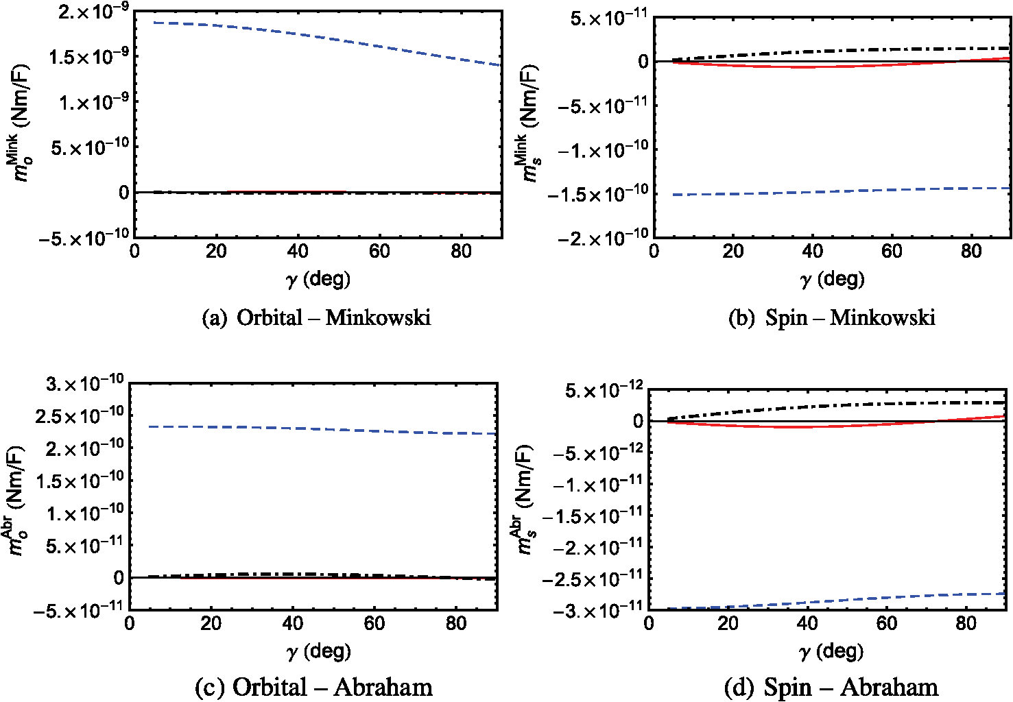 A scan of Fig. 2(a) shows that the magnitude of the -directed component of is significantly larger than the magnitudes of its - and -directed components; therefore, is predominantly directed along an axis (-axis) that lies wholly in the interface plane and is oriented perpendicular to the direction of propagation. Similarly, a scan of Fig. 2(c) shows that is also oriented very similarly. But, and in Figs. 2(b) and 2(d), respectively, are oriented along the -axis. A comparison of Figs. 2(a) and 2(b) with Figs. 2(c) and 2(d) shows that the magnitudes of the Cartesian components of the Minkowski orbital and spin angular momentums generally exceed those of their Abraham counterparts. The magnitudes of as functions of are presented in Fig. 3. The spin angular momentum is weaker than the orbital angular momentum in both the Minkowski and Abraham formulations. Furthermore, and . 3.4.Periodically Nonhomogeneous Anisotropic Partnering Dielectric MaterialLet us now consider that the half-space is occupied by an SNTF with a periodically nonhomogeneous relative permittivity dyadic20 where the dyadics depend on the sinusoidally varying vapor incidence angle As the third dyadic on the right side of Eq. (28) is given by Eq. (24), the morphologically significant plane of the SNTF is also formed by the unit vectors and .Following Parts I, II, IV, and V, an SNTF made by evaporating patinal titanium oxide34 was considered with where . The following quantities were fixed for all numerical results presented here: , , and . Let us note that the CTF considered in Sec. 3.3 can be treated as a special case of the SNTF considered in this section with .The real and imaginary parts of the relative wavenumbers obtained by the solution of the dispersion equation [Eq. (10)] are provided in Fig. 4 as functions of . These solutions have been reproduced from Part IV.19 Either two or three SPP waves can be guided by the metal/SNTF interface, depending on the angle between the direction of propagation and the morphologically significant plane of the SNTF. The SPP waves guided by the metal/SNTF interface are neither - nor -polarized, except when . Fig. 4The real and imaginary parts of relative wavenumbers as functions of for SPP waves guided by a metal/SNTF interface.19 The metal is bulk aluminum, whereas the chosen SNTF is described in Sec. 3.4. 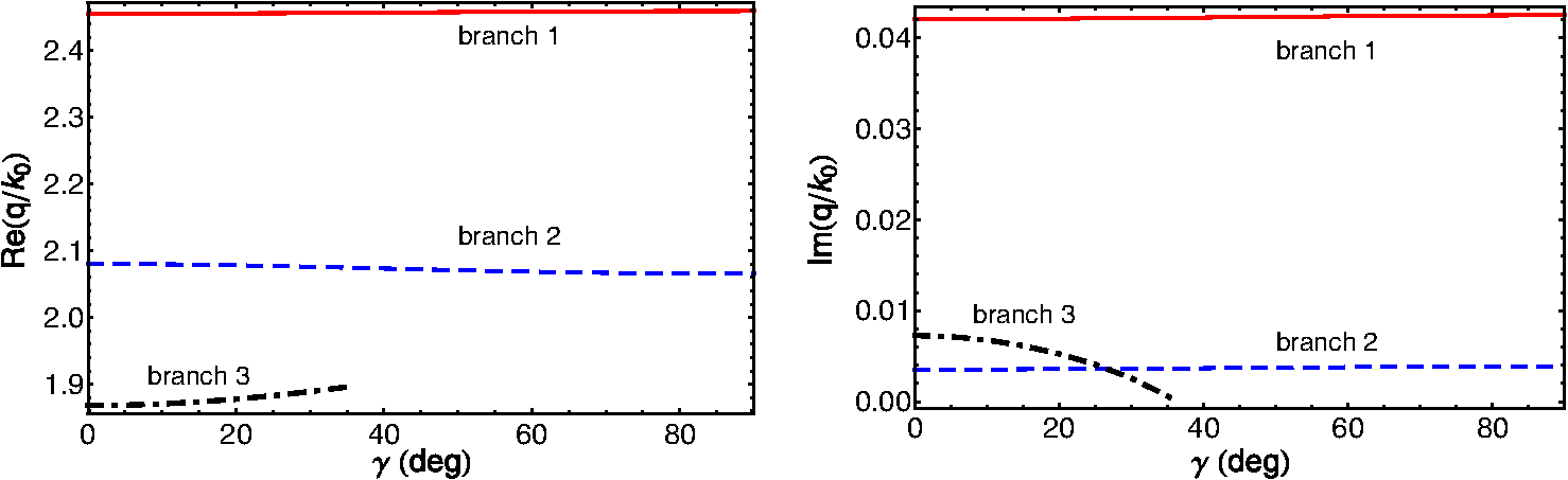 3.4.1.When , two - and one -polarized SPP waves can be guided by the metal/SNTF interface. The values of the relative wavenumber and the -components of are provided in Table 2. Table 2Relative wavenumbers q/k0 and y-directed components of ms,oMink,Abr of SPP waves guided by the interface of bulk aluminum and the chosen titanium-oxide SNTF when γ=0 deg and λ0=633 nm. The values of Nd used in Eq. (18) are also provided. The x- and z-directed components of ms,oMink,Abr are identically zero. The computations were made by setting {ap=1,as=0} V/m for p-polarized SPP waves and {ap=0,as=1} V/m for s-polarized SPP waves.
For both -polarized SPP waves, and are anti-parallel in both the Minkowski and Abraham formulations. Furthermore, both parts of the angular momentum are directed along an axis that lies wholly in the interface plane and is oriented perpendicular to the direction of propagation—in accord with a -polarized SPP wave guided by either a metal/isotropic-dielectric or a metal/CTF interface when . For the only -polarized SPP wave, is identically zero in both the Minkowski and Abraham formulations. As was found for the interface of a metal and an isotropic dielectric partnering material—whether homogeneous (Sec. 3.1) or periodically nonhomogeneous (Sec. 3.2)—the magnitudes of the Minkowski spin and orbital angular momentums are higher than those of their Abraham counterparts; furthermore, the magnitudes of increase significantly as the phase speed of the SPP wave increases. 3.4.2.For , the Cartesian components of are plotted in Fig. 5 for the SPP waves guided by the chosen metal/SNTF interface for the solutions on branch 1 in Fig. 4. The -directed component of is greater in magnitude than the other components of ; therefore, can be said to lie in the interface plane and oriented perpendicular to the direction of propagation. A similar remark can also be made for , , and , though is directed opposite to . A comparison of Figs. 2 and 5 shows that the angular momentum of the SPP wave represented by branch 1 in Fig. 4 for the metal/SNTF interface and for the sole SPP wave guided by the metal/CTF interface are similar in magnitudes and directions, in both formulations. Fig. 5The Cartesian components of (a) , (b) , (c) , and (d) as functions of for solution branch 1 (in Fig. 4) representing the SPP waves guided by the interface of bulk aluminum and the chosen titanium-oxide SNTF when . The -, -, and -directed components are represented by red solid, blue dashed, and black chain-dashed lines, respectively. For computations, was set after ascertaining that the values of the Cartesian components of and converged. 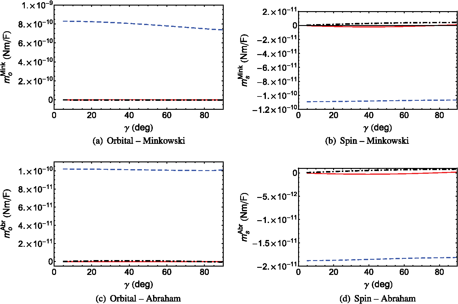 For the SPP waves on branch 2, the Cartesian components of are plotted in Fig. 6 as functions of . A scan of Figs. 6(a) and 6(c) shows that the orbital angular momentum lies almost wholly in the interface plane and is perpendicular to the direction of propagation. However, lies in the -plane, because the - and -directed components of are similar in magnitude and are greater in magnitude than the -directed component [Fig. 6(b)]. Similarly, also lies in the -plane. A comparison of Figs. 5 and 6 shows that the Cartesian components of the angular momentums of SPP waves on branch 2 are significantly larger than of those on branch 1. The Cartesian components of for branch 3 are presented only for in Fig. 7 for convenience, because the magnitude of either one or two components increases rapidly as increases from 30 deg to 36 deg. Figures 7(a) and 7(c) show that the orbital angular momentum is directed perpendicular to the direction of propagation and lies in the interface plane, because the -directed component is larger in magnitude than the - and -directed components in both formulations. Similarly, Figs. 7(b) and 7(d) show that and are directed along the -axis when is small and lie in the -plane when is large. From Figs. 5–7, we conclude that all Cartesian components of and are nonzero for , in contrast to the case when . The nonzero - and -directed components are also in contrast with the results presented in Secs. 3.1 and 3.2. The magnitudes of as functions of are presented in Fig. 8 for all three branches of solutions in Fig. 4. A quick scan of Fig. 8 shows the availability of a wide range of magnitudes of and in both the Minkowski and Abraham formulations for different SPP waves guided by the metal/SNTF interface. A comparison of Figs. 8(a), 8(c), and 8(e) with Figs. 8(b), 8(d), and 8(f) indicates that the magnitude of the spin angular momentum is lower than that of the orbital angular momentum in both formulations. Moreover, the Minkowski orbital and spin angular momentums are larger in magnitude than their Abraham counterparts. These trends are similar to the cases when partnering dielectric material is either isotropic (Secs. 3.1 and 3.2) or homogeneous and anisotropic (Sec. 3.3). Fig. 8The magnitudes of as functions of of SPP waves guided by the interface of bulk aluminum and the chosen titanium-oxide SNTF when . The panels (a, b), (c, d), and (e, f) correspond to the solution on branches labeled 1, 2, and 3 in Fig. 4. For computations, for branch 1, 6 for branch 2, and 10 for branch 3 were set after ascertaining that the values of the Cartesian components of and converged. Results for the Abraham and Minkowski formulations are denoted by red solid and blue dashed lines, respectively. 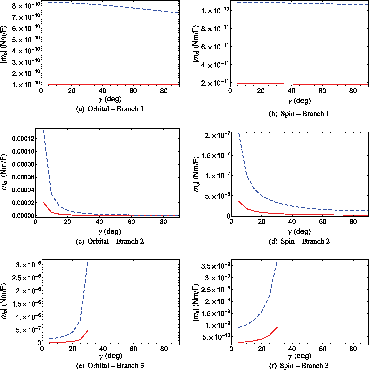 Analysis of Fig. 8 and Tables 1 and 2 shows that the magnitudes of are generally higher when the SPP waves are neither - nor -polarized, except for the SPP waves on branch 1 guided by the metal/SNTF interface. Parenthetically, we note that the polarization state of the SPP waves on branch 1 is very near to the -polarization state,19 which may explain the lower magnitudes of the spin and orbital angular momentums for SPP waves on this branch. Of all the SPP waves guided by metal/SNTF interface, the SPP waves on branch 2 generally have the highest magnitudes of the spin and orbital angular momentums in both formulations. A comparison of the results presented in Sec. 3.3 for the metal/CTF interface and in this section for the metal/SNTF interface shows that:
Let us note that the comparison between the results for the metal/CTF and metal/SNTF interfaces is quite appropriate, because the relative permittivity dyadic of the SNTF can be transformed into the relative permittivity dyadic of the CTF by setting . Parenthetically, we note that the conclusions derived by using an SNTF of patinal titanium oxide as the partnering dielectric material should not change qualitatively even if the SNTF were to be considered as made by evaporating another dielectric material, because many of the interesting features of an SPP wave guided by a metal/SNTF interface result from the SPP wave not being linearly polarized. 4.Concluding RemarksThe time-averaged spin and orbital parts of the angular momentums of multiple SPP waves guided by the interface of a metal and a periodically nonhomogeneous SNTF were theoretically investigated using the solutions of the underlying canonical boundary-value problem. Multiple SPP waves propagate not only with different phase speeds, attenuation rates, and spatial field profiles (in particular, the degree of localization to the interface in the SNTF), but also with different magnitudes and directions of the spin and orbital parts of the angular momentum—calculated using either of the two formulations: one due to Minkowski and the other due to Abraham. The magnitudes and directions of the angular momentums of SPP waves guided by a metal/SNTF interface can vary over large ranges. For all SPP waves guided by the metal/SNTF interface, the orbital angular momentum lies in the interface plane and is oriented perpendicular to the direction of propagation. For the SPP waves on branch 1, the spin angular momentum is similarly directed. For the SPP waves on branch 2, the spin angular momentum lies in the plane formed by the direction of propagation and normal to the interface; for the SPP waves on branch 3, it is perpendicular to the direction of propagation but does not lie in the interface plane. The magnitude of the spin angular momentum is less than that of the orbital angular momentum, in both formulations. Furthermore, the magnitudes of both the spin and the orbital angular momentums are higher for the SPP waves guided by the metal/SNTF interface (when the propagation of SPP waves does not take place in the morphologically significant plane) than the metal/rugate-filter interface. The magnitudes of the spin and orbital parts of the Minkowski angular momentum were found to be larger than of their Abraham counterparts. The replacement of an isotropic, homogeneous, partnering dielectric material by an isotropic, periodically nonhomogeneous, partnering dielectric material does not change the direction of the spin and orbital parts of the angular momentums of SPP waves, but the magnitudes are certainly enhanced. At the same time, periodic nonhomogeneity engenders a multiplicity of SPP waves. The replacement of an anisotropic, homogeneous, partnering dielectric material by an anisotropic, periodically nonhomogeneous, partnering dielectric material not only engenders a multiplicity of SPP waves and significantly enhances the magnitudes of the spin and orbital parts of the angular momentums of SPP waves, but it also affords numerous directions for those quantities. The conclusions on the spin and orbital angular momentum densities obtained here through the solution of the canonical boundary-value problem should hold for the prism-coupled configuration17 as long as the partnering materials are sufficiently thick in that configuration.14 However, the results could be somewhat different for the grating-coupled configuration,20 due to the presence of multiple Floquet modes arising from the periodic corrugation of the interface of the partnering materials. Let us note in closing that the relative permittivity dyadic of the SNTF can be engineered during fabrication.25 Therefore, the magnitudes and the directions of the spin and the orbital parts of the angular momentum can be engineered. This flexibility in the design of SNTFs—not to mention sculptured thin films of other types25—and the choices of the spin and the orbital angular momentums thereby available may have potential for the trapping and rotation of single molecules that infiltrate the partnering SNTF. Furthermore, in microfluidic channels, metal/SNTF microflakes could be used for directed transportation of molecules stowed inside the porous SNTF, the translation and rotation of each microflake effected through a beam of light. AcknowledgmentsMuhammad Faryad and Akhlesh Lakhtakia are grateful for the partial support from Grant No. DMR-1125591 of the US National Science Foundation. Akhlesh Lakhtakia is also grateful to Charles Godfrey Binder Endowment at The Pennsylvania State University for the partial support of this work. ReferencesS. J. van EnkG. Nienhuis,
“Eigenfunction description of laser beams and orbital angular momentum of light,”
Opt. Commun., 94
(1–3), 147
–158
(1992). http://dx.doi.org/10.1016/0030-4018(92)90424-P OPCOB8 0030-4018 Google Scholar
N. B. Simpsonet al.,
“Mechanical equivalence of spin and orbital angular momentum of light: an optical spanner,”
Opt. Lett., 22
(1), 52
–54
(1997). http://dx.doi.org/10.1364/OL.22.000052 OPLEDP 0146-9592 Google Scholar
L. MarrucciC. ManzoD. Paparo,
“Optical spin-to-orbital angular momentum conversion in inhomogeneous anisotropic media,”
Phys. Rev. Lett., 96
(16), 163905
(2006). http://dx.doi.org/10.1103/PhysRevLett.96.163905 PRLTAO 0031-9007 Google Scholar
Twisted Photons: Applications of Light with Orbital Angular Momentum, Wiley-VCH, Weinheim, Germany
(2011). Google Scholar
Surface Plasmon Resonance Based Sensors, Springer, Heidelberg, Germany
(2006). Google Scholar
A. Kinkhabwalaet al.,
“Large single-molecule fluorescence enhancements produced by a bowtie nanoantenna,”
Nat. Photonics, 3
(11), 654
–657
(2009). http://dx.doi.org/10.1038/nphoton.2009.187 1749-4885 Google Scholar
J. SeidelS. GrafströmL. Eng,
“Stimulated emission of surface plasmons at the interface between a silver film and an optically pumped dye solution,”
Phys. Rev. Lett., 94
(17), 177401
(2005). http://dx.doi.org/10.1103/PhysRevLett.94.177401 PRLTAO 0031-9007 Google Scholar
T. HolmgaardS. I. Bozhevolnyi,
“Dielectric-loaded plasmonic waveguide components,”
Plasmonics and Plasmonic Metamaterials: Analysis and Applications, 305
–333 World Scientific, Singapore
(2012). Google Scholar
P. Berini,
“Integrated optics based on long-range surface plasmon polaritons,”
Surface Plasmon Nanophotonics, 217
–233 Springer, Dordrecht, The Netherlands
(2007). Google Scholar
A. RuryR. Freeling,
“Angular momentum conservation in plasmonics,”
in Proc. Conf. Lasers and Electro-Optics (CLEO),
(2012). Google Scholar
A. Liuet al.,
“Encoding photonic angular momentum information onto surface plasmon polaritons with plasmonic lens,”
Opt. Express, 20
(22), 24151
–24159
(2012). http://dx.doi.org/10.1364/OE.20.024151 OPEXFF 1094-4087 Google Scholar
M. Liuet al.,
“Light-driven nanoscale plasmonic motors,”
Nat. Nanotechnol., 5
(8), 570
–573
(2010). http://dx.doi.org/10.1038/nnano.2010.128 1748-3387 Google Scholar
M. FaryadA. Lakhtakia,
“On surface plasmon-polariton waves guided by the interface of a metal and a rugate filter with a sinusoidal refractive-index profile,”
J. Opt. Soc. Am. B, 27
(11), 2218
–2223
(2010). http://dx.doi.org/10.1364/JOSAB.27.002218 JOBPDE 0740-3224 Google Scholar
M. R. M. AtallaM. FaryadA. Lakhtakia,
“On surface plasmon-polariton waves guided by the interface of a metal and a rugate filter with a sinusoidal refractive-index profile. Part II: high-phase-speed solutions,”
J. Opt. Soc. Am. B, 29
(11), 3078
–3086
(2012). http://dx.doi.org/10.1364/JOSAB.29.003078 JOBPDE 0740-3224 Google Scholar
M. Faryadet al.,
“Excitation of multiple surface-plasmon-polariton waves guided by the periodically corrugated interface of a metal and a periodic multilayered isotropic dielectric material,”
J. Opt. Soc. Am. B, 29
(4), 704
–713
(2012). http://dx.doi.org/10.1364/JOSAB.29.000704 JOBPDE 0740-3224 Google Scholar
M. A. MotykaA. Lakhtakia,
“Multiple trains of same-color surface plasmon-polaritons guided by the planar interface of a metal and a sculptured nematic thin film,”
J. Nanophotonics, 2 021910
(2008). http://dx.doi.org/10.1117/1.3033757 JNOACQ 1934-2608 Google Scholar
M. A. MotykaA. Lakhtakia,
“Multiple trains of same-color surface plasmon-polaritons guided by the planar interface of a metal and a sculptured nematic thin film. Part II: Arbitrary incidence,”
J. Nanophotonics, 3 033502
(2009). http://dx.doi.org/10.1117/1.3147876 JNOACQ 1934-2608 Google Scholar
A. LakhtakiaY.-J. JenC.-F. Lin,
“Multiple trains of same-color surface plasmon-polaritons guided by the planar interface of a metal and a sculptured nematic thin film. Part III: Experimental evidence,”
J. Nanophotonics, 3 033506
(2009). http://dx.doi.org/10.1117/1.3249629 JNOACQ 1934-2608 Google Scholar
M. FaryadJ. A. Polo Jr.A. Lakhtakia,
“Multiple trains of same-color of surface plasmon-polaritons guided by the planar interface of a metal and a sculptured nematic thin film. Part IV: Canonical problem,”
J. Nanophotonics, 4 043505
(2010). http://dx.doi.org/10.1117/1.3365052 JNOACQ 1934-2608 Google Scholar
M. FaryadA. Lakhtakia,
“Multiple trains of same-color of surface plasmon-polaritons guided by the planar interface of a metal and a sculptured nematic thin film. Part V: Grating-coupled excitation,”
J. Nanophotonics, 5 053527
(2011). http://dx.doi.org/10.1117/1.3663210 JNOACQ 1934-2608 Google Scholar
J. A. Polo Jr.A. Lakhtakia,
“On the surface plasmon polariton wave at the planar interface of a metal and a chiral sculptured thin film,”
Proc. R. Soc. Lond. A, 465
(2101), 87
–107
(2009). http://dx.doi.org/10.1098/rspa.2008.0211 PRLAAZ 0080-4630 Google Scholar
A. Lakhtakia,
“Surface multiplasmonics,”
Proc. SPIE, 8104 810403
(2011). http://dx.doi.org/10.1117/12.893129 PSISDG 0277-786X Google Scholar
S. E. SwiontekD. P. PulsiferA. Lakhtakia,
“Optical sensing of analytes in aqueous solutions with a multiple surface-plasmon-polariton-wave platform,”
Sci. Rep., 3 1409
(2013). http://dx.doi.org/10.1038/srep01409 SRCEC3 2045-2322 Google Scholar
M. FaryadA. Lakhtakia,
“Enhancement of light absorption efficiency of amorphous-silicon thin-film tandem solar cell due to multiple surface-plasmon-polariton waves in the near-infrared spectral regime,”
Opt. Eng., 52
(8), 087106
(2013). http://dx.doi.org/10.1117/1.OE.52.8.087106 OPEGAR Google Scholar
A. LakhtakiaR. Messier, Sculptured Thin Films: Nanoengineered Morphology and Optics, SPIE Press, Bellingham, Washington
(2005). Google Scholar
V. A. YakubovichV. M. Starzhinskii, Linear Differential Equations with Periodic Coefficients, Wiley, New York, New York
(1975). Google Scholar
Y. Jaluria, Computer Methods for Engineering, Taylor & Francis, Washington, DC
(1996). Google Scholar
E. A. HindsS. M. Barnett,
“Momentum exchange between light and a single atom: Abraham or Minkowski?,”
Phys. Rev. Lett., 102
(5), 050403
(2009). http://dx.doi.org/10.1103/PhysRevLett.102.050403 PRLTAO 0031-9007 Google Scholar
R. N. C. Pfeiferet al.,
“Momentum of an electromagnetic wave in dielectric media,”
Rev. Mod. Phys., 79
(4), 1197
–1216
(2007). http://dx.doi.org/10.1103/RevModPhys.79.1197 RMPHAT 0034-6861 Google Scholar
S. M. BarnettR. Loudon,
“The enigma of optical momentum in a medium,”
Philos. Trans. R. Soc. Lond. A, 368
(1914), 927
–939
(2010). http://dx.doi.org/10.1098/rsta.2009.0207 PTRMAD 1364-503X Google Scholar
S. M. Barnett,
“Resolution of the Abraham–Minkowski dilemma,”
Phys. Rev. Lett., 104
(7), 070401
(2010). http://dx.doi.org/10.1103/PhysRevLett.104.070401 PRLTAO 0031-9007 Google Scholar
M. PadgettS. M. BarnettR. Loudon,
“The angular momentum of light inside a dielectric,”
J. Mod. Opt., 50
(10), 1555
–1562
(2003). http://dx.doi.org/10.1080/09500340308235229 JMOPEW 0950-0340 Google Scholar
J. A. Polo Jr.A. Lakhtakia,
“Morphological effects on surface-plasmon-polariton waves at the planar interface of a metal and a columnar thin film,”
Opt. Commun., 281
(21), 5453
–5457
(2008). http://dx.doi.org/10.1016/j.optcom.2008.07.051 OPCOB8 0030-4018 Google Scholar
I. J. HodgkinsonQ. H. WuJ. Hazel,
“Empirical equations for the principal refractive indices and column angle of obliquely deposited films of tantalum oxide, titanium oxide, and zirconium oxide,”
Appl. Opt., 37
(13), 2653
–2659
(1998). http://dx.doi.org/10.1364/AO.37.002653 APOPAI 0003-6935 Google Scholar
Biography Xuerong Xiao received her BS degree in engineering science at The Pennsylvania State University, University Park, Pennsylvania, in May 2013. She graduated with honors and with highest distinction. Her thesis was on angular momentums of multiple surface-plasmon-polariton waves. She is currently a doctoral student in electrical engineering at Stanford University.  Muhammad Faryad received his MSc and MPhil degrees in electronics from the Quaid-i-Azam University, Pakistan, in 2006 and 2008, respectively, and the PhD degree in engineering science and mechanics from The Pennsylvania State University, University Park, Pennsylvania, in 2012. Currently, he is a postdoctoral research scholar at The Pennsylvania State University. His research interests include sculptured thin films, solar cells, and electromagnetic surface waves. He is a member of Optical Society of America and SPIE.  Akhlesh Lakhtakia received degrees from the Banaras Hindu University (BTech and DSc) and the University of Utah (MS and PhD) in electronics engineering and electrical engineering, respectively. He is the Charles Godfrey Binder (Endowed) professor of Engineering Science and Mechanics at The Pennsylvania State University, University Park, Pennsylvania, and presently serves as the editor-in-chief of the Journal of Nanophotonics. His current research interests include nanotechnology, bone refacing, bioreplication, forensic science, surface multiplasmonics, and complex materials including metamaterials and sculptured thin films. He is a fellow of SPIE, Optical Society of America, American Association for the Advancement of Science, American Physical Society, and Institute of Physics (UK). He received the 2010 SPIE Technical Achievement Award. |