|
|
|
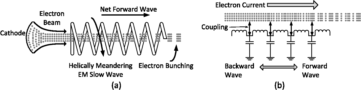
Advances in computational power over the last few decades have dramatically opened up the modeling capability of the typical researcher. Although laborious analysis and approximations of physical systems were quite the norm some decades ago, today complex problems can be simulated extensively before being built or committed to design. Today, the pursuit of computational experimentation has displaced, to a large extent, either laboratory experimentation or extensive theoretical analysis, especially in systems in which the governing equations are well developed. Indeed, in the field of electromagnetics (EM), where only select canonical problems are amenable to analytical solutions, computer simulations have allowed for great flexibility in searching for new applications to Maxwell’s equations. In light of this flexibility, however, one should not abandon completely either the approaches or models researchers have developed over the years. Consider the large body of work pertaining to electron devices, especially that related to traveling wave devices such as traveling wave tubes and backward wave oscillators (BWOs). These devices attempt to generate or amplify propagating EM energy through coupled interaction with a guided electron beam. The theory for these devices was developed without the benefit of computer simulation, and much effort went into constructing models that could be both (relatively) easily manipulated and understood in terms of traditional electrical engineering concepts such as impedance, power, phase propagation constants, and so on. Pierce was a primary proponent of this approach, and his simplifying concepts are valid today, over a half century later.1 The propagation of guided EM waves in this case is modeled through a simple lumped-element analogue to a transmission line. These waves interact with the electron beam as described from the Lorentz force equations. In order to handle the nonlinearity of the Lorentz equations, the beam-wave interaction equations are linearized by expanding quantities such as electron velocities and induced currents into a dc component with a small, perturbing ac component. All nonlinear components are discarded, and the resulting dc and ac parts of the equations are separated and matched. The resulting sets of equations are analytically tractable. While this approach might seem somewhat arbitrary as all behavior that is difficult to solve (all nonlinear time-dependent behavior) is simply discarded, the result has proven both intuitive and useful. In some sense, it is like having a coarse terrain map of electron device behavior to which a variety of EM structures can be coupled and their resulting systems predicted. Accuracy is discarded in lieu of intuition. At the time, this approach was taken due to necessity; now, however, it is possible to use such an approach followed by a full-system simulation. Consider, for example, the conceptual models of the traveling-wave devices as shown in Fig. 1. Fig. 1The omega-beta (dispersion) diagram of the helix slow-wave structure along with the beam interaction points. The diagram repeats in 2π as the guided fields were expanded in a Fourier series over the period of the helix (the pitch P). 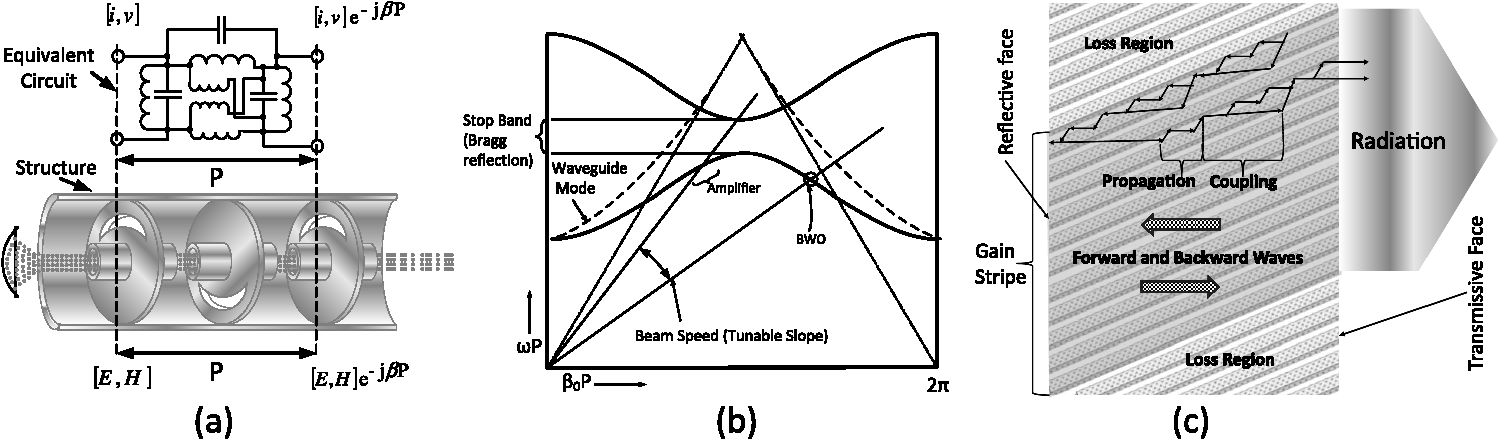 A focused electron beam is guided through the center of a wire helix, referred to as a slow-wave circuit. An EM propagating wave travels in a helical path around the beam so that the propagating electric fields of the guided wave are slowed to be almost in lock-step with that of the electron beam. Continuous interaction between the propagating wave and the beam electrons lead to a periodic bunching as shown. The electron beam speed is slightly larger than the reduced propagation constant of the EM wave so that the circuit coupling results in a drag force on the beam to extract energy and slow the beam down. The Pierce model shown in Fig. 2(b) captures this behavior by using lumped-element inductors and capacitors in a periodic array. This circuit is identical to the model most of us are familiar with in an introduction to transmission line theory. Coupling the transmission line to the electron beam results in a periodic injection of current along the line, and this periodic coupling causes traveling-wave amplification or oscillation, depending on the system. Conventional parameters that appear from the transmission-line model are useful in this case as well: the impedance of the transmission line, the phase propagation constant of a traveling wave, as well as the group speed defining the propagation of energy along the line. Consider that this approach provides a means to understand a wide range of traveling wave devices as well as a way to decouple the slow-wave circuit design from the system design. The slow-wave circuit is an electromagnetic guiding structure that is periodic in space, and decomposing the EM wave into a series of Fourier space harmonics allows us to construct a dispersion diagram, Brillouin diagram, or omega-beta diagram as it is called in the electron tube industry.2 The Pierce model defines a way to judge the performance of a particular structure through an interaction impedance that relates the axial electric field component of a harmonic at the electron beam to the current induced by this harmonic. An omega-beta diagram for the helix is shown in Fig. 1 illustrating the beam/harmonic interaction. The omega-beta diagram shows two components of the space harmonic, periodic in , and the resulting dispersion of the helix in each region. At any point in the dispersion curve, the phase and group speeds can be calculated from (phase speed) and from (group speed). The interaction of the space harmonic with the electron beam is seen by plotting the electron speed as a constant slope depending on its value (called beam voltage). Changing the slope of the beam line produces different interaction locations with the space harmonic and different device operation. When the beam line lies along the flat part of the helix dispersion, both the phase speed (interaction) and group speed (power flow) are positive in slope. The beam and space harmonic flow in the same direction to produce a growing traveling wave. The region as shown creates a traveling-wave amplifier. When the beam line crosses the downward sloping space harmonic, the phase speed of the harmonic is positive, while the group speed is negative. This crossing point produces an oscillation in which the space harmonic phase matches the positive beam speed, but the actual power flow is in the negative direction. This device, called a BWO, extracts energy at the start of the helix. The output frequency () is tunable by changing the beam voltage. Two examples of structures and interactions analogous to that of the helix structure above are shown in Fig. 3. Fig. 3Active devices and their interaction structures. The coupled cavity traveling wave tube (a), its corresponding omega-beta diagram and interaction points (b), and a top view of the tilted Bragg grating distributed feedback laser (c).3 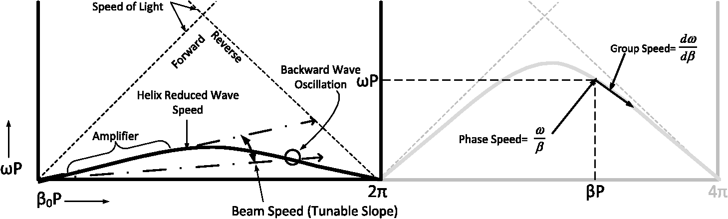 The two devices operate through the interaction of a periodic structure coupled to an active medium. The coupled cavity is the simplest to correlate to a lumped-element model circuit that describes the EM wave’s propagation and coupling behavior over one period (P). The resulting omega-beta diagram shows the expected behavior, and its solution can be analytically determined by circuit analysis to reasonably correlate to actual cavity structures.4 Only a single period is needed since the periodicity of the cavities allows one to use Floquet’s theorem in which the EM fields (and circuit equivalents) differ in one period by a complex propagation constant , assuming lossless transmission. Note that the omega-beta diagram provides much of the expected behavior of the device. Amplification in the coupled cavity is over a narrow band where the electron beam line and the forward-propagating wave interact; backward-wave oscillation is possible as well over a tunable frequency range. Also notice that the behavior resembles a parabolic waveguide dispersion [dotted line in Fig. 3(b)] that is periodic in with interaction or bending of the waveguide modes where their dispersion curves cross. Such behavior is typical of periodic structures wherever coupling can occur among propagating waves, and it is simple to approximate based on the symmetry, periodicity, and expected coupling of the structure. Also notice in the dispersion curves that regions can exist where values of frequency () do not have propagating solutions. These regions are called stop bands, and they correspond to reflections from the periodic cavities that result in a standing EM wave with no net power flow. Such regions, shown at in Fig. 3(b), are analogous to Bragg reflections perpendicular to a grating. Figure 3(c) shows a tilted grating distributed feedback laser (DFB) that uses such a periodically doped substrate tilted to the side walls. The grating is analogous to a flattened helix structure in which the spiraling field is no longer able to complete the spiral. Indeed, similar structures such as interdigital lines, combs, slot, and rings have been extensively explored for electron device interaction.5 Mostly, the tradeoff in structure in these devices is between broadband operation (as in the complete helix) and power handling capabilities (as in the coupled-cavity). For the DFB device, narrow-band filtering is needed to suppress unwanted lasing modes, and thus gratings are used at selected resonant-like conditions. Considering Fig. 3(c), the similarities between the helix and the tilted grating are evident. Wave propagation along the grating channels interact with the optical gain region. Propagation across the grating couples the channels and distribute the growing optical wave across the gain stripe. This coupling is similar to that of the helix and coupled cavity, and similar circuit models can be constructed using a distributed model coupled with a Floquet analysis. The analogies and approaches presented are not new or unknown in the literature. However, periodic advances in materials, fabrication capabilities, and the rapid miniaturization of structures should cause us to reconsider the existing body of literature. In particular,
It is hoped that such approaches can lead to not only better performing devices based on current technologies, but also a range of new devices based on the application of well-explored, but rapidly disappearing technologies. ReferencesJ. R. Pierce,
“Traveling-wave tubes,”
Bell Syst. Tech. J., 29
(1), 1
–59
(1950). http://dx.doi.org/10.1002/bltj.1950.29.issue-1 BSTJAN 0005-8580 Google Scholar
L. Brillouin, Wave Propagation in Periodic Structures, Dover, New York
(1953). Google Scholar
R. J. Langet al.,
“Theory of grating-confined broad-area lasers,”
IEEE J. Quantum Electron., 34
(11), 2196
–2210
(1998). http://dx.doi.org/10.1109/3.726614 IEJQA7 0018-9197 Google Scholar
H. J. Curnow,
“A general equivalent circuit for coupled-cavity slow-wave structures,”
IEEE Trans. Microw. Theory, 13
(5), 671
–675
(1965). http://dx.doi.org/10.1109/TMTT.1965.1126062 IETMAB 0018-9480 Google Scholar
A. F. Harvey,
“Periodic and guiding structures at microwave frequencies,”
IRE Trans. Microw. Theory Tech., 8
(1), 30
–61
(1960). http://dx.doi.org/10.1109/TMTT.1960.1124658 IRMTAK 0097-2002 Google Scholar
|